14 minutes
Writing a Chip-8 Emulator
Emulators were a staple of my childhood. I played a variety of classic games on emulators to pass the time. I have always wondered what went into creating an emulator. Research led me to discover that CHIP-8 was an easy platform to develop an emulator for. Further research led me to discover a program that ran CHIP-8 binaries would technically be an interpreter and not an emulator since CHIP-8 programs were run on a virtual machine and not hardware. This post is a summary of my experience writing a CHIP-8 emulator in Rust.
Disassembler
CHIP-8 has 35 opcodes. All of the opcodes are two bytes long and stored in big-endian format. The first step to writing an emulator would be familiarizing myself with these opcodes. I could do that by writing a disassembler. I chose to write the disassembler in Rust because I wanted to learn the language. A disassembler takes the binary file and converts it to assembly. The CHIP-8 does not have an official assembly language, as a result, I used the pseudo-C code in the Wikipedia opcode table. The disassembler was fairly straightforward. I first opened the binary file.
let file = fs::read(&args[1]);

let mut counter =0;

let file = file.expect("File could not be opened");
I then iterated over every two bytes in the file. A match statement then identified the relevant opcode and printed it. The first byte of the CHIP-8 opcode states which kind of instruction is being performed. The other bytes could represent memory addresses, registers, or 8-4 bit constants.
I wrote three helper functions to extract specific bytes from the full opcode.
// return any specific byte from an opcode.

fn get_byte(abyte:i32, opcode:u16 ) ->u16 {

  match abyte{

    0=> return opcode >> 12,

    1=> return (opcode << 4) >>12,

    2=> return (opcode <<8 ) >>12,

    3=>return opcode& 0xF,

    _=> return 1,

  }

}

// returns the 12-bit address specified in opcodes like jump

fn get_addr(opcode:u16) -> u16{

  return opcode & 0xFFF;

}

// returns 8-bit constants specified in instructions like if

fn get_last_two(opcode:u16) -> u8{

  return (opcode & 0xFF) as u8;

}
The dissembler prints the corresponding pseudo-C code for each opcode in the binary.
while counter < file.len() {

    let opcode = ((file[counter] as u16) << 8) | file[counter+1] as u16;

    let intial_byte = file[counter] >> 4;

    match nibble {

      0 =>{ if opcode ==0x00E0 { println!("disp_clear()")

      };

      if opcode == 0xEE {println!("ret")};}

      1 => println!("goto {:x}",get_addr(opcode)),

      2=> println!("*({:x})()", get_addr(opcode) ),

      3=> println!("if register:{} == {:x}",get_byte(1, opcode), get_last_two(opcode)),

--SNIP--

      _=> print!("")

    }

    counter= counter+2;
Running the disassembler through on a random ROM led to an output that looked like so:
V5=0

disp_clear()

V3 = rand() & 255

 I = 546

set_BCD (v3)

reg_load(v2,&I)

V4=0

I sprite_addr [v0]

draw(V4, V5, 5)

v4 += 5

I sprite_addr [v1]

draw(V4, V5, 5)

v4 += 5

I sprite_addr [v2]

draw(V4, V5, 5)

v3= get_key()

goto 202
The output looked reasonably correct. Testing other ROMs, I noticed some opcodes within the files were not being recognized. After a bit of research, I realized that data was for drawing sprites. I was ready to implement the CHIP-8 hardware and start executing instructions.
Minimum Viable Emulator
CHIP-8 “Hardware”
I created a CHIP-8 struct to simulate all the hardware needed to run CHIP-8 instructions.
struct Chip8 {

// all the general purpose registers(V0-VF). The 16th register VF is a flag register set to one to indicate things like collision.

  v: [u8;16],

// Index register used to hold address values used for certain opcodes.

  I: u16,

  // A stack pointer used to indicate where new entries can be added to the stack

  SP: u16,

  //The program counter which indicates the current instruction in memory.

  PC:u16,

  //The delay timer is decremented once a clock tick.

  delay: u8,

  //The sound timer beeps as long as the timer is not zero.

  sound: u8,

  //4 kilobytes of RAM for the CHIP-8

  memory: [u8;4096],

  //The display is a 64 by 32 grid of pixels that can be on or off.

  display:[bool;64*32],

  //The stack implemented outside of the emulated memory

  stack: [u16;16],

  //A variable to keep track of which keys are being pressed.

  keys: [bool;16],

}
Next, I implemented a new function for the CHIP-8 struct. The program counter is set to 0x200 where the ROM will be loaded into memory. All other variables are initialized to zero.
impl Chip8 {

  fn new() -> Chip8{

    return Chip8 {

      SP:0,

      PC: 0x200,

      delay:0,

      sound:0,

      v: [0;16],

      I:0,

      memory:[0;4096],

      display: [false;64*32],

      stack:[0;16],

      keys:[false;16],

    };

  }
The push and pop functions for the stack are then implemented.
fn push(&mut self, value: u16 ) {

self.stack[self.SP as usize]=value;

self.SP+=1;

}

fn pop(&mut self) -> u16{

let address =self.stack[(self.SP-1) as usize];

self.SP-=1;

return address;

}
Finally, I was ready to load a ROM and the font set into memory. The font set consists of sprite data for printable characters. It is required because the CHIP-8 emulator is responsible for its own font set. The fontset can be stored anywhere in the first 512 bytes of memory which is reserved for the emulator. The code that is below loads the ROM and font set into memory:
  fn load_rom(&mut self, rom: Vec<u8>){

    let mut counter =0;

    self.memory[..80].copy_from_slice(&FONTSET);

    while counter< rom.len(){

      self.memory[(self.PC as usize+ counter) ]= rom[counter];

      counter+=1;

    }

  }
The font set is below:
const FONTSET: [u8; 80] = [

  0xF0, 0x90, 0x90, 0x90, 0xF0, // 0

  0x20, 0x60, 0x20, 0x20, 0x70, // 1

  0xF0, 0x10, 0xF0, 0x80, 0xF0, // 2

  0xF0, 0x10, 0xF0, 0x10, 0xF0, // 3

  0x90, 0x90, 0xF0, 0x10, 0x10, // 4

  0xF0, 0x80, 0xF0, 0x10, 0xF0, // 5

  0xF0, 0x80, 0xF0, 0x90, 0xF0, // 6

  0xF0, 0x10, 0x20, 0x40, 0x40, // 7

  0xF0, 0x90, 0xF0, 0x90, 0xF0, // 8

  0xF0, 0x90, 0xF0, 0x10, 0xF0, // 9

  0xF0, 0x90, 0xF0, 0x90, 0x90, // A

  0xE0, 0x90, 0xE0, 0x90, 0xE0, // B

  0xF0, 0x80, 0x80, 0x80, 0xF0, // C

  0xE0, 0x90, 0x90, 0x90, 0xE0, // D

  0xF0, 0x80, 0xF0, 0x80, 0xF0, // E

  0xF0, 0x80, 0xF0, 0x80, 0x80 // F

];
After that, I was ready to write the function that fetches and executes instructions from memory. Four bytes are fetched from the address in the PC. The opcode is created with some bit-shifting. A match statement then mutates the state of the CHIP-8 struct to perform the correct instruction. Lastly, the PC is incremented twice to point to the next opcode.
fn fetch_execute(&mut self){

let opcode=((self.memory[self.PC as usize ] as u16) << 8) | self.memory[(self.PC+1) as usize] as u16;

--SNIP match statement from disassembler--

// finally we increment the program counter by two

self.PC+=2;
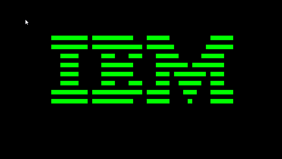
The new goal was to implement a few of the easier opcodes. Just enough opcodes to run the IBM logo program. Which only required the following opcodes:
00E0(clear screen)1NNN(jump)6XNN(set registerVX)7XNN(add value to registerVX)ANNN(set index register)DXYN(display/draw)
Later I discovered there was a CHIP-8 splash screen program that did not use 7XNN the instruction which would be an easier target for the first program to run. I left the display instruction to be implemented last due to its complexity.
// inside match statement

 0 =>{

 if opcode ==0x00E0 {

 //Clearing the screen turns off all pixels in the display

 self.display= [false;64*32];

          };

// Jump sets the PC to a 12-bit address. The PC is preemptively decremented to stop the opcode from being skipped. At the end of the match statement, the PC is incremented, but should not be after a jump.

1 => {self.PC=get_addr(opcode); self.PC-=2;},

--SNIP--

// The register VX is set to NN

 6=> {self.v[get_byte(1, opcode) as usize]=get_last_two(opcode);},

 // A value NN is added to the register VX

7=> self.v[get_byte(1, opcode) as usize]=(get_last_two(opcode) as u16 +self.v[get_byte(1, opcode) as usize]as u16)as u8,

//The index register is set to a 12-bit address

0xA=> {self.I= get_addr(opcode);},
The dreaded Display Instruction
Lastly, the display instruction had to be attempted. Before Implementing the instruction I had to figure out how to display things to the screen in Rust. After some reading, I settled on using the Rust sdl2 library. I found a [tutorial] (https://blog.logrocket.com/using-sdl2-bindings-rust/) on using the library to create a snake game to learn how to draw pixels to the screen. First, I initialize a window that is 64 units by 32 units with a dot size in pixels of 20. Future me should make the pixel size customizable.
const GRID_X_SIZE: u32 = 64;

  const GRID_Y_SIZE: u32 = 32;

  const DOT_SIZE_IN_PXS: u32 = 20;

  let sdl_context = sdl2::init()?;

  let video_subsystem = sdl_[context.video](http://context.video)().expect("video");

  let mut window = video_subsystem

  .window(

    "chip 8",

    GRID_X_SIZE * DOT_SIZE_IN_PXS,

    GRID_Y_SIZE * DOT_SIZE_IN_PXS

  )

  .position_centered()

  .opengl()

  .build()

  .map_err(|e| [e.to](http://e.to)_string()).expect("map");

  // renderer is a helper struct???

  let mut gfx = Renderer::new(window).expect("render");
Next, the main loop of drawing the screen could be written. I first listened for any keyboard events. The program sleeps to slow down the emulation to a reasonable rate. Original CHIP-8 displays ran at 60 Hz. Next, an instruction is fetched and executed. Finally, the display is drawn using the draw screen function.
 'running: loop {

     for event in event_pump.poll_iter() {

      match event {

--SNIP--

    }

    // sleep 120 times per second

    ::std::thread::sleep(Duration::new(0, 1_000_000_000u32 / 120));

    Chip8.fetch_execute();

    gfx.draw_screen(Chip8.display);

  }
The draw screen function iterates over the display array. A square is drawn where a turned-on pixel should be.
  fn draw_screen(&mut self, display: [bool;64*32] ){

    self.canvas.set_draw_color(Color::BLACK);

    self.clear();

    self.canvas.set_draw_color(Color::GREEN);

    let mut counter=0;

    while counter < display.len(){

      if display[counter]{

      //converts from 1d array to 2d coordinates.

        let x = counter %64;

        let y = counter /64;

        self.canvas.fill_rect(Rect::new(

          x as i32* [self.DOT](http://self.DOT)_SIZE_IN_PXS as i32 ,

          y as i32* [self.DOT](http://self.DOT)_SIZE_IN_PXS as i32,

          [self.DOT](http://self.DOT)_SIZE_IN_PXS,

          [self.DOT](http://self.DOT)_SIZE_IN_PXS,

        )).expect("");

      };

      counter+=1;

      }

      //Displays the canvas we have drawn to the screen.

       self.canvas.present();

      self.canvas.set_draw_color(Color::BLACK);

  }
I tested the draw_screen function by manually turning on some pixels. I was ready to implement the CHIP-8 display function. It proved to be harder than initially thought it would be. I found this Reddit thread to be most helpful in understanding how the instruction was supposed to work. The display instruction takes two registers X and Y and a number N which is how tall the sprite will be. Care must be taken to use the value in the register and not X or Y directly.
// This register is set 1 one if sprites collide

self.v[0xf]=0;

let x_register_number= get_byte(1, opcode);

let y_register_number= get_byte(2, opcode);

let x_position = self.v[x_register_number as usize] %64;

let y_position = self.v[y_register_number as usize] %32;

let rows = get_byte(3, opcode);
For every row N, I must get the Nth byte of sprite data counting from the address in the Index register I.
for sprite_row in 0..rows {

let sprite_row_data= self.memory[(self.I + sprite_row)as usize];
For every bit in the byte, I check if the bit would be drawn within the bounds of the display.
for bit in 0..8{

if (x_position+bit < 64) & ((y_position+ sprite_row as u8) < 32){
Next, the 2d x and y positions are converted into a 1d index for the display array.
let index:u16 = (x_position +bit) as u16 +((y_position as u16+sprite_row as u16)*64)as u16;

let screen_pixel = self.display[index as usize];

let sprite_pixel = (sprite_row_data & (1 <<7 - bit)) !=0;
The pixel being drawn and the pixel currently on the display are compared. If both pixels are on, then the VF register is set to one. VF indicates two sprites have collided. The collided pixel is then turned off. Most of my initial confusion was because I did not realize the screen pixel should be turned off in the event of a collision.
if sprite_pixel & screen_pixel{

self.v[0xf] =1;

self.display[index as usize]=false;

}
If the pixel from the sprite data is on and the pixel on the screen is not then the pixel on the display is turned on.
if sprite_pixel & !screen_pixel{

self.display[index as usize]=true;

}
After implementing the display instruction, I could run the splash screen ROM and the IBM logo ROM. As a result, 6/35 opcodes were implemented.
Test suites
I next found a CHIP-8 test suite. I took a first stab at implementing most opcodes covered by Corax+ opcode test which consists of math operations, if statements, and saving and loading registers.
If Statements
The CHIP-8 if statements are simple. If the condition is true, the next instruction is skipped. This is normally paired with a jump command to redirect the flow of execution.
//3xnn skip if VX=NN

if self.v[get_byte(1, opcode) as usize]==get_last_two(opcode){

self.PC+=2;

}
Jump Commands
2NNN calls a subroutine at the memory address NNN. The current PC is pushed onto the stack, and the PC is set to the address in the opcode. Finally, the PC is decremented to compensate for the PC being incremented after the match statement.
self.push(self.PC);

self.PC=get_addr(opcode);

self.PC-=2;
After a bit of work, I got all the instructions to pass the initial checks.
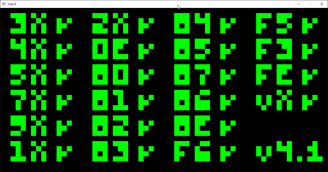
Next, I focused on the flag test which focuses on corner cases involving the VF register in arithmetic instructions. It checks each opcode for:
correctness of the output
if the VF flag is set correctly
if the case where the VY register is VF is handled correctly
if the case where the VY register is VF is handled correctly
Overall my implementation of most arithmetic instructions did not set the carry flag correctly. The VF register should be set last. Setting it too early will result in the calculation being wrong when VF is one of the operands. Additionally, care must be taken to prevent buffer over and underflows to avoid runtime errors in rust.
// Example of the subtraction instruction

let orignal_vx = self.v[get_byte(1, opcode) as usize];

let orignal_vy= self.v[get_byte(2, opcode) as usize];

// wrapping_sub is used to prevent buffer overflow runtime errors

let answer = self.v[get_byte(2, opcode) as usize].wrapping_sub(self.v[get_byte(1, opcode) as usize]);

self.v[get_byte(1, opcode) as usize]=answer;

if orignal_vx<= orignal_vy{

self.v[0xf]=1;

}

else{

self.v[0xf]=0;

}
Results of the first arithmetic test:
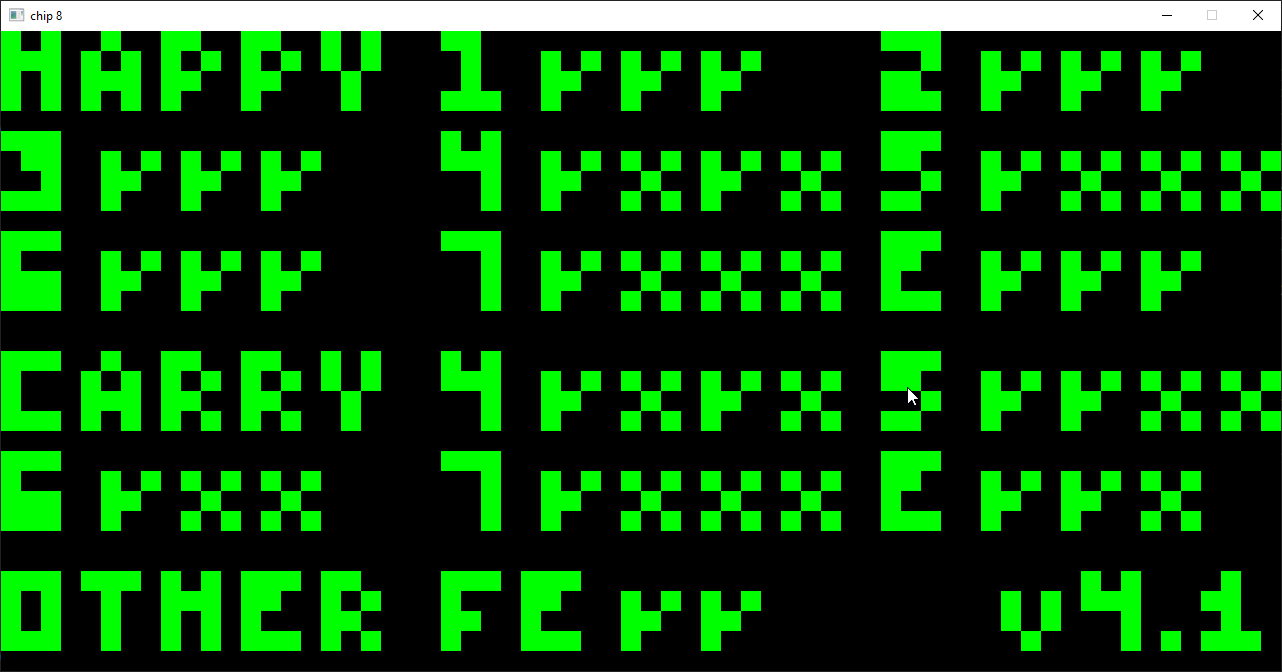
I worked my way through all the other arithmetic functions squashing minor bugs until all tests were passed. 25/35 opcodes implemented.

User Input
Now, it was time to deal with user input. If a key is pressed down, the corresponding element in the keys array is set to true and false otherwise.
  'running: loop {

    for event in event_pump.poll_iter() {

      match event {

        Event::Quit { .. } => break 'running,

        Event::KeyUp {

          keycode: Some(keycode),..

        }=> match keycode {

          Keycode::Num1=> Chip8.keys[1]=false,

          Keycode::Num2=> Chip8.keys[2]=false,

          Keycode::Num3=> Chip8.keys[3]=false,

          Keycode::Num4=> Chip8.keys[0xc]=false,

          // row two

          Keycode::Q=> Chip8.keys[4]=false,

--SNIP--

          _ => {},

        },

        Event::KeyDown {

          keycode: Some(keycode),

          ..

        } => match keycode{

          Keycode::Num1=> Chip8.keys[1]=true,

          Keycode::Num2=> Chip8.keys[2]=true,

          Keycode::Num3=> Chip8.keys[3]=true,

          Keycode::Num4=> Chip8.keys[0xC]=true,

          // row two

          Keycode::Q=> Chip8.keys[4]=true,

--SNIP--

          _=>{}

        }

        _ => {}

      }

    }
EX9E and EXA1 Skip if key
Three CHIP-8 instructions deal with keyboard input. The EX9E command skips the next command if the key in the VX register is pressed. EXA1 skips the next command if the key is not pressed.
//EX9E

let register_value= self.v[get_byte(1, opcode)as usize];

if !self.keys[register_value as usize]{

self.PC+=2;

}
FX0A: Get Key
FX0A pauses execution until a key is pressed then stores that key in the VX register.
if !self.keys.contains(&true){

self.PC-=2;

}

else{

for i in 0..15{

if self.keys[i as usize]{

self.v[get_byte(1, opcode)as usize]=i;

break;

}

}
Timers
Now, timer-related instructions could be implemented. FX07, FX15, and FX18 were trivial to implement. All were variants of setting timers to the value of registers or vice versa. An update timer function was added to the main game loop.
fn update_timers(&mut self){

if self.delay > 0{

      self.delay -=1;

    }

     if self.sound > 0 {

       println!("beep");

      self.sound -=1;

    }

  }
After every tick, the timers are decremented once. The CHIP-8 beeps while the sound timer is above zero. I then needed to figure out how to actually play a sound. I wound up using the soloud audio engine.
```rust
let sl = Soloud::default().expect(“audio”);
let mut wav = <soloud::audio::Wav as soloud::AudioExt>::default();
// loading an mp3 file to be played
soloud::LoadExt::load(&mut wav, &std::path::Path::new("beep.mp3")).expect(“audio load”);
Attempting the play the sound from the update timer function resulted in borrow checking related compile errors. This error was remedied by borrowing the needed variables. The first implementation below resulted in multiple instances of the beeping sound playing over each other at once.

```rust

if self.sound > 0 {

if sl.voice_count()==0{

[sl.play](http://sl.play)(wav);

}
I discovered sl had a voice_count property I could check to ensure the beep only played once.
if self.sound > 0 {

if sl.voice_count()==0{

[sl.play](http://sl.play)(wav);

}
At this point, I had implemented all of the CHIP-8 opcodes. While each opcode was not too difficult to implement, it was satisfying to see all the pieces fit together. It was fun to play some games to test the finished emulator. My favorite to play so far was breakout. I would recommend writing a CHIP-8 to anyone who wants to explore the inner workings of retro machines. It can also serve as an interesting first project in a new programming language for someone with prior experience in programming. Rust was pleasant to program in, and the borrow checker proved to not be too annoying to deal with. While I am done with the CHIP-8 emulator for now, I’m sure further improvements could be made. Next time I pick up this project I will focus on making the emulator more configurable. I would like to add alternative versions of instructions, the ability to change key binds and frame rates, and add a debugging interface. In the mean time, you can view the repo here.
2886 Words
2024-04-25 17:00